Content
For engineers and procurement teams comparing composite insulator options, the direct answer is this: for long span high voltage transmission lines rated between 10kV and 500kV, a composite suspension insulator is the correct choice; for substation busbars, switchgear and distribution equipment, a composite post insulator such as the FZSW series performs better than a suspension type; for crossarm mounting on transmission poles, a composite pin insulator interchanges directly with a traditional porcelain pin insulator without modifying the pole hardware; and for catenary systems on electrified railways, a dedicated railway insulator is required to isolate the pantograph and overhead conductors. Across all four types, a composite insulator outperforms a traditional porcelain insulator in weight, pollution flashover resistance and installation speed, which is why composite insulator specifications now dominate new builds and retrofit projects across the power transmission and rail electrification sectors.
A composite insulator is an insulating component used in high voltage equipment within power systems, applied across transmission lines, substations and electrified railways. Its job is simple to state and demanding to engineer: support the conductor, keep current from leaking to ground, and stay stable through decades of weather cycling. A composite insulator is built from three parts working together, and the performance of the finished unit depends on how well those three parts are matched.
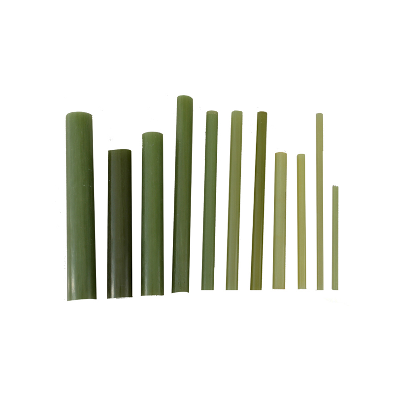
The core rod sits at the center of the insulator and is made from acid resistant, high temperature resistant epoxy fiberglass. It is the primary load bearing element, carrying the mechanical tensile force of the conductor. A well made core rod has high strength, a high elastic modulus, and resistance to corrosion and aging, which is why the rod quality is usually the first thing a technical buyer checks on a datasheet.
The sheds, typically molded from silicone rubber, form the ring shaped or disc shaped umbrella structure along the rod. Large, medium and small sheds alternate to extend the creepage distance without extending the physical length of the unit. Textured grooves on the shed surface improve hydrophobicity and drainage, which is the property that lets water bead up and roll off rather than forming a continuous conductive film across the surface.
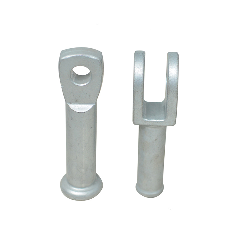
Metal fittings sit at each end of the insulator, usually hot dip galvanized steel or stainless steel with a rare earth aluminum coating. They are joined to the core rod using a crimping process engineered to prevent detachment from stress concentration or corrosion, since a fitting failure is the most common cause of an in service insulator failure.
Selecting a composite insulator is a matching exercise between the electrical environment, the mechanical load, and the mounting geometry already on site. Five factors decide the outcome on almost every project.
Selection checklist
1. Rated voltage of the line or busbar, from 10kV distribution up to 500kV and above transmission.
2. Rated mechanical tensile or bending load the fitting needs to carry in normal and fault conditions.
3. Pollution level of the site, which drives the required creepage distance and shed profile.
4. Mounting orientation, meaning suspended in a string, mounted vertically as a post, or fixed horizontally as a pin type.
5. Climate exposure, including high altitude, coastal salt fog, or severe cold and freezing rain.
Voltage and mechanical load are usually fixed by the line design, so the real decision most buyers face is between suspension, pin, post and railway families, and within a family, which creepage distance and mechanical class fits a specific pollution zone. A site with heavy industrial pollution or coastal salt spray needs a longer creepage distance at the same voltage class, which is why the same 110kV rating can appear across several structure heights in a single product line.
Taizhou HuaDong Insulated Material Co., Ltd manufactures four composite insulator families covering transmission, substation and railway applications, engineered around the same core rod and silicone rubber shed technology described above.
The comparison that decides most tenders is composite against porcelain. A composite insulator wins on weight, pollution flashover behavior and speed of installation. A porcelain insulator still holds an edge on raw compressive strength and thermal mass in some post applications, which is why porcelain has not disappeared entirely from substation specifications, even as composite becomes the default for new suspension and pin hardware.
| Property | Composite Insulator | Porcelain Insulator |
| Relative Weight | 1/7 to 1/10 of porcelain at the same rating | Baseline reference weight |
| Pollution Flashover Resistance | Strong, hydrophobic silicone rubber sheds | Moderate, needs regular cleaning |
| Mechanical Strength | High tensile strength, high bending failure load | High compressive strength |
| Aging Resistance | Validated by 5000 hour artificial aging tests | Stable but brittle over time |
| Installation and Handling | Lightweight, faster crew installation | Heavier, more handling equipment needed |
| Maintenance Frequency | Low, self cleaning shed surface | Higher, periodic washing recommended |
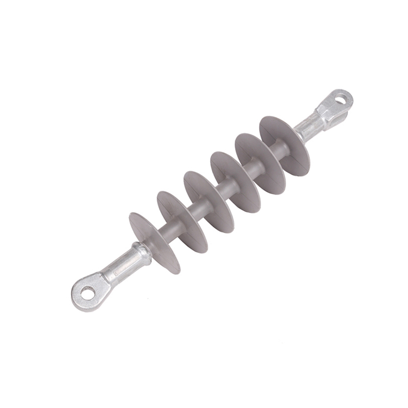
A composite suspension insulator hangs from a suspension clamp through a ball head, with the socket end connected to the tower or crossarm. It covers voltage classes from 10kV up to 500kV and above, and can be strung in series for higher voltage requirements, or arranged as vertical strings, V shaped strings, or tension strings. It is the preferred choice for polluted areas, long spans, compact line corridors and sites with high mechanical tensile loads.
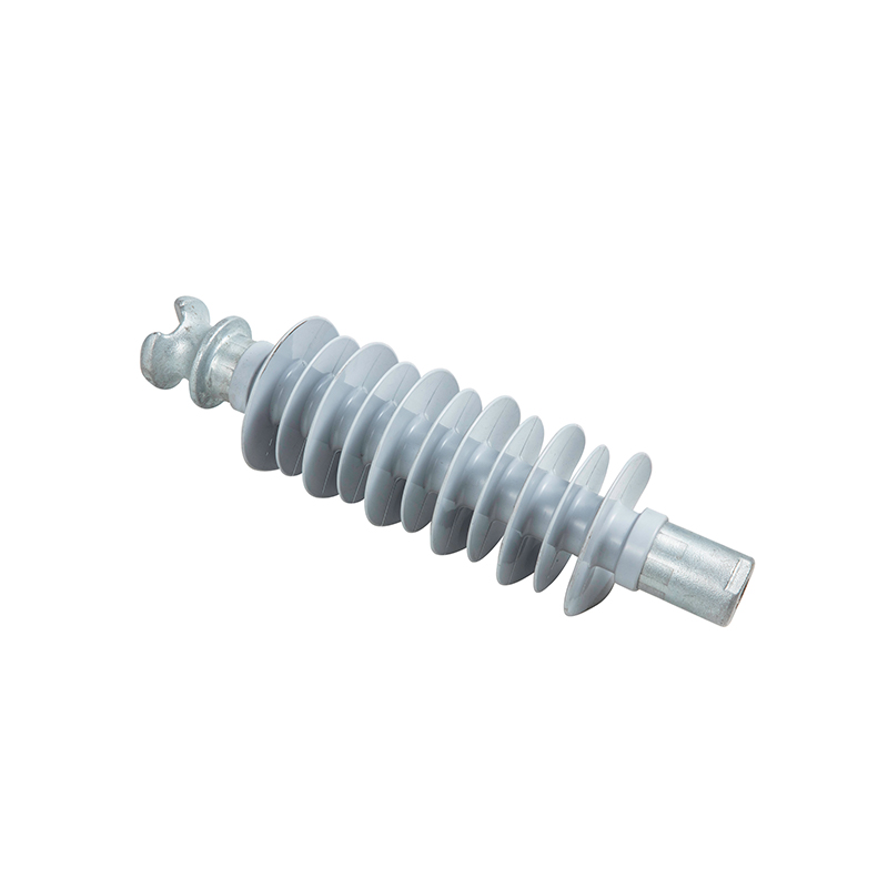
A composite pin insulator uses a core rod, silicone rubber housing and metal fittings in a compact profile designed for direct crossarm mounting. Its top and bottom mounting dimensions match a traditional porcelain pin insulator, so it can replace an existing unit without modifying the pole or crossarm. It is well suited to high humidity areas, heavily polluted corridors, corrosive coastal air, and high altitude zones where cleaning access is limited.
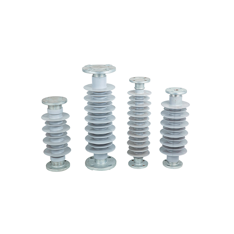
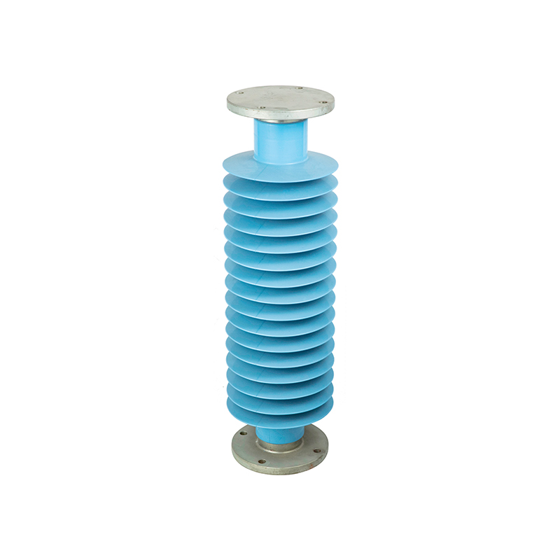
A composite post insulator is a vertical support column used inside substations, holding busbars, circuit breakers and disconnect switches while providing electrical isolation. The FZSW series covers 10kV through 220kV, with bending loads from 4kN to 10kN and creepage distances from 540mm to 6300mm, and the mounting hole center distance stays fixed at 127mm with an 18mm hole diameter across the range, which keeps hardware consistent as a substation is expanded or upgraded.
A railway insulator isolates high voltage conductors, overhead contact line equipment and substation apparatus inside electrified railway systems. Suspension type railway insulators support bracket arms, positioners and section insulators on the catenary, post type units support traction substation busbars and switches, and roof mounted units insulate the pantograph from the vehicle body. Because a railway corridor often passes through varied terrain, railway insulators are specified with additional resistance to pollution, humidity, altitude and cold in a single product line.
Four measurable advantages explain why composite insulator specifications keep expanding into segments that used porcelain for decades.
Weight and size — a composite unit weighs only 1/7 to 1/10 of an equivalent porcelain insulator, cutting transport cost and reducing the structural load carried by the tower or support column.
Mechanical performance — high bending failure load and tensile strength combine with a simple structure that resists damage during transport and installation.
Weather and aging resistance — validated through 5000 hour artificial aging tests and high altitude simulation, confirming reliability across long service periods.
Hydrophobic surface — silicone rubber sheds cause water to bead rather than sheet across the surface, which is the mechanism behind strong anti pollution flashover performance even when the shed surface is contaminated.
The sheds and core rod are produced using an integral molding process that avoids voids at the interface, preventing electric field concentration and partial discharge inside the unit. Metal fittings are attached by a crimping process engineered for both mechanical strength and electrical continuity, so the finished insulator behaves as one continuous component rather than three parts bolted together.
The table below lines up representative models across voltage classes so a specifier can compare mechanical load and creepage distance side by side before requesting a full datasheet.
| Model | Rated Voltage | Mechanical Load | Creepage Distance |
| FXBW4-10/70 | 10kV | 70kN | 450mm |
| FXBW4-110/100 | 110kV | 100kN | 3280mm |
| FXBW4-220/160 | 220kV | 160kN | 6350mm |
| FXBW-500/300 | 500kV | 300kN | 14750mm |
| FZSW-35/4 | 35kV Post | 4kN Bending | 625mm |
| FZSW-220/8 | 220kV Post | 8kN Bending | 6300mm |
Reading this table alongside the selection checklist above gives a specifier three numbers to confirm before shortlisting a model: the rated voltage of the line or busbar, the mechanical load the fitting must survive, and the creepage distance required for the site pollution class. Once those three numbers are fixed, the choice between suspension, pin, post and railway families is decided by mounting geometry rather than electrical performance, since all four families share the same core rod and silicone rubber shed technology described earlier in this article.
Composite insulator technology has moved from a niche alternative to the default specification for transmission, substation and railway electrification projects because it solves the same three problems porcelain always struggled with: weight, pollution flashover and long term maintenance cost. Matching voltage class, mechanical load and creepage distance to the site conditions, then selecting the suspension, pin, post or railway family that fits the mounting geometry, is the complete decision path covered in this guide.
Contact Us

jszn@vip.163.com
jsthim@188.com

0086 523-88026699
0086 523-88665172



Quick Links
Product Categories
Message Us Now !