Content
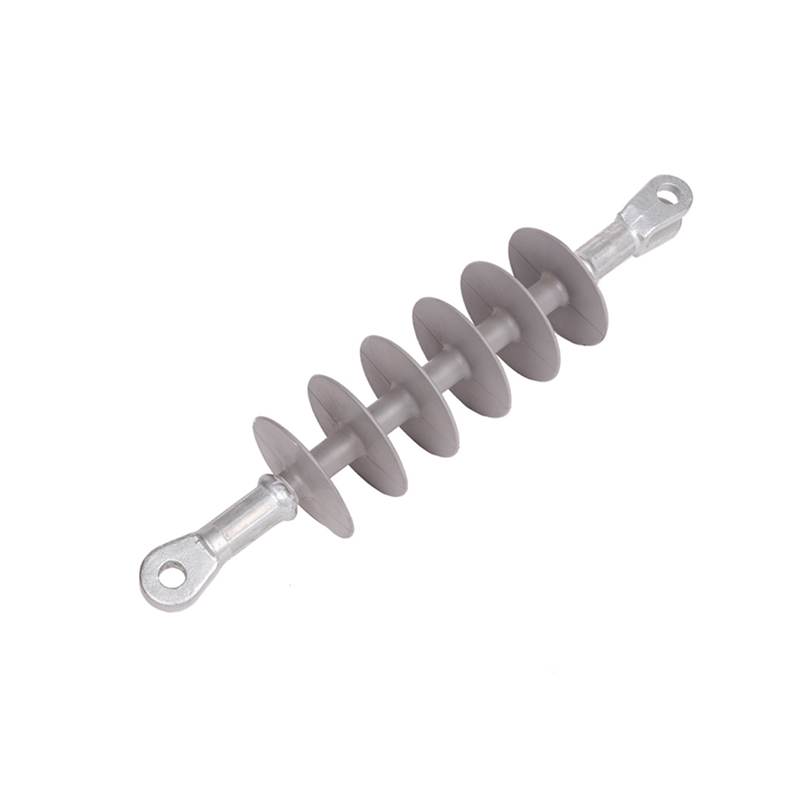
A 24 kV cutout fuse can pass a routine factory test and still fail in service when moisture reaches a machined end. The fuse body is rarely the weak point; the glass fiber-reinforced core profile inside it often is. In composite insulators, railway supports, and live-line hardware, that core is both the load-bearing spine and the dielectric barrier. Buyers who treat it as a commodity rod tend to pay later through creep, tracking, or end-fitting pull-out.
The practical rule is simple: specify the core as an engineered profile, not as “FRP rod” by diameter alone. Fix the resin system, fiber content, dimensional tolerance, surface condition, end sealing, and batch test evidence before you compare price.
In electrical hardware, the term usually describes a pultruded or wound glass-fiber reinforcement set in a thermoset matrix, most often epoxy for insulator cores. The glass supplies tensile and flexural strength; the resin transfers load between fibers, blocks moisture, and gives the surface its dielectric behavior. A good profile is therefore a system: fiber, sizing, resin, cure, and machining must work together.
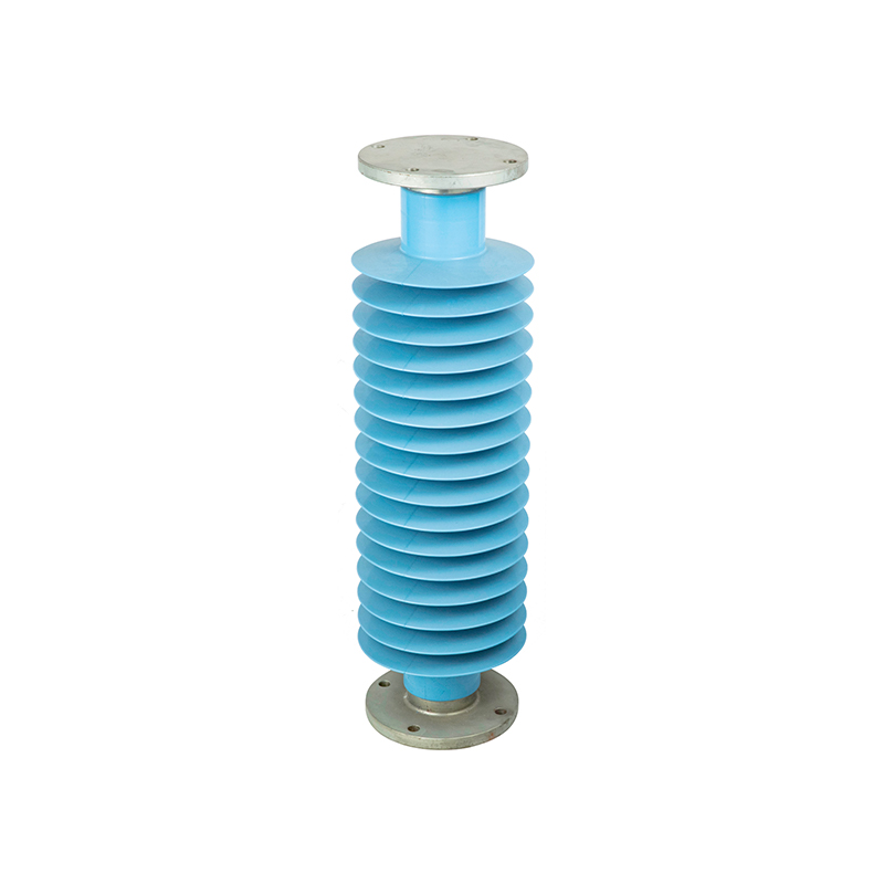
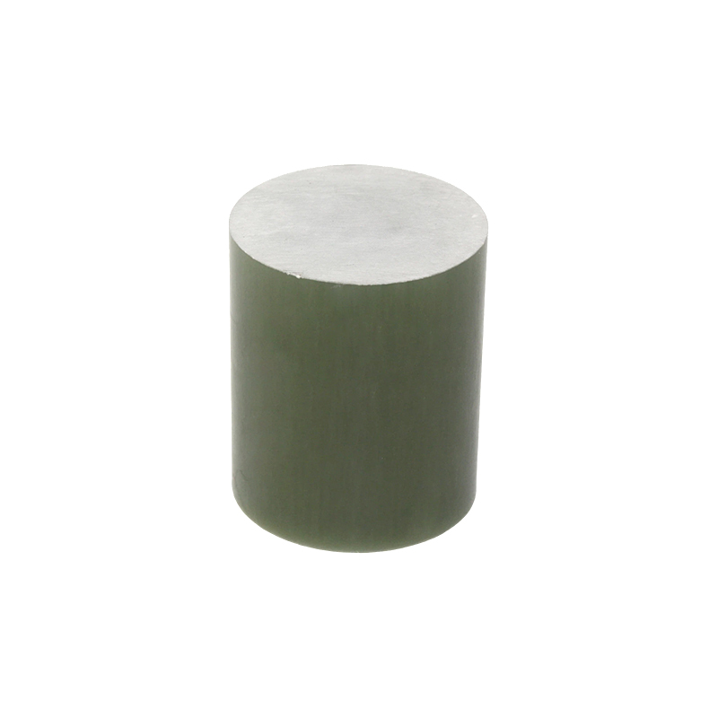 Glass-Fiber Epoxy Core Rod for Composite InsulatorsThe load-bearing glass-fiber core at the center of composite insulators, made with epoxy resin and checked for profile quality before housing and fittings are added.View Product →
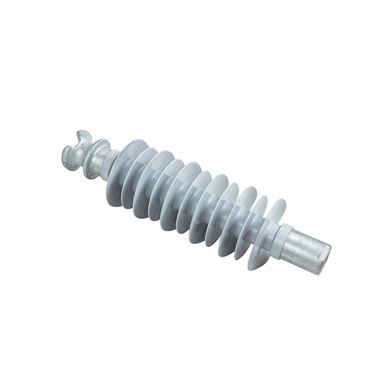
The word “profile” matters. A commodity FRP rod may meet a nominal diameter and still have ovality, resin-rich surface patches, or exposed fiber at a cut end. Those defects are tolerable in a decorative part and unacceptable in a high-voltage core. For insulator production, the core is often an epoxy glass fiber rod that later receives silicone housing, crimped metal end fittings, or both.
A core failure rarely looks like a core problem at first. It appears as a flashover, a loose end fitting, a cracked shed, or an unexplained increase in leakage current. The table below links common core decisions to the field risk they control.
| Specification area | What it controls | Practical purchasing action |
|---|---|---|
| Fiber/resin interface and void content | Partial discharge, moisture wicking, mechanical fatigue | Ask for void content or microsection evidence; reject chalky, dry, or resin-starved surfaces. |
| Diameter, ovality, straightness | Crimp interference, concentricity, fitting alignment | Put tolerance on the drawing; do not accept generic commercial rod tolerance for a crimped insulator core. |
| Surface finish and cut-end sealing | Bonding to housings, moisture ingress, tracking | Define surface cleanliness and sealed or capped ends; inspect for longitudinal ridges and exposed fiber. |
| Thermal and mechanical match | Cracking at metal fittings, creep under sustained load | Check tensile, flexural, and creep data plus thermal expansion against the fitting material. |
| Electrical evidence | Dielectric strength, tracking, erosion | Require wet and dry electrical test reports on the actual batch, not a generic datasheet. |
The fastest way to reduce rework is to write the core profile into the drawing as a controlled component. The following sequence works for composite insulators, fuse gear, and railway supports because it forces the supplier to quote against the same requirements.
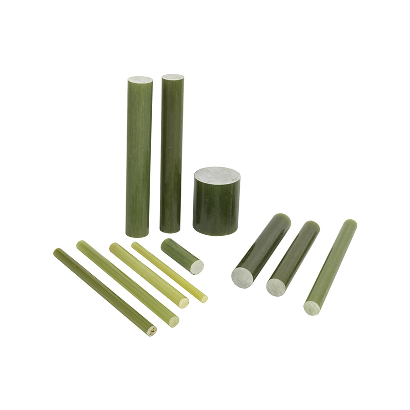
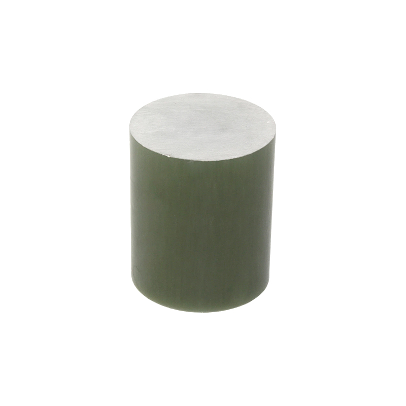 Custom Epoxy Fiberglass Rod for Insulator CoresA pultruded glass-fiber rod with epoxy matrix, offered in multiple diameters and colors for core profiles that need high strength and electrical insulation.View Product →
A supplier should be willing to quote to your drawing, not ask you to choose from a generic rod list. The FRP rod range is organized by product format, but the drawing and test plan still decide whether the part is suitable.
Pultrusion is continuous, but the quality is not uniform by default. Glass roving tension, resin bath viscosity, die temperature, line speed, and post-cure all affect fiber wet-out and void content. A small change in line speed can shift the resin-rich layer or leave dry fiber inside the core.
Look for process controls that are specific to core profiles: diameter gauging, resin mix records, cure verification, and mechanical testing on the finished rod rather than on a generic sample. The quality system should also show how nonconforming lots are segregated. A certificate is useful; a batch-linked test report is more useful.
Suppliers that cite IEC 61109, GB/T 19519, or JB/T 8460 should map each report to the actual core batch and the finished insulator design, not to a different diameter or resin system. For practical checks on rod selection, the FRP rod profile selection guide covers drawing details and supplier questions. The same logic applies to wound tubes and finished insulators: the earlier the interface is defined, the fewer the surprises at assembly.
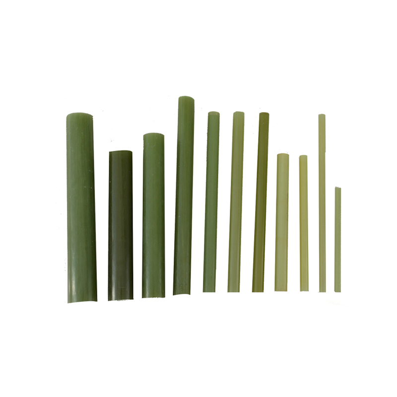
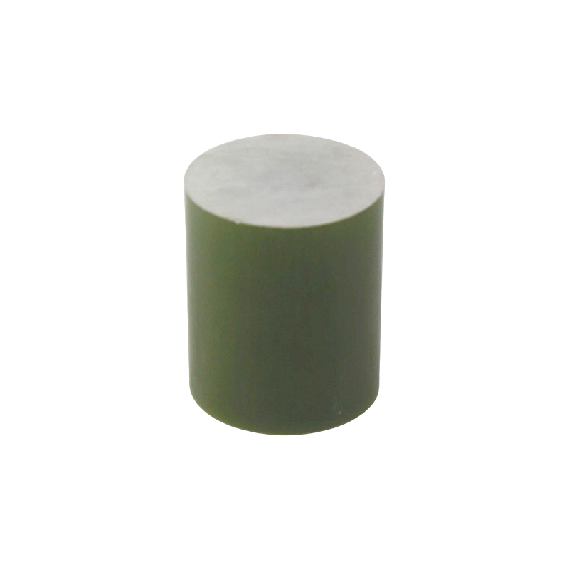 Fiberglass FRP Rods for Insulation and Structural UseAn FRP rod family in epoxy or polyester, supplied in cylindrical or custom profiles for electrical, chemical, and structural parts needing insulation and corrosion resistance.View Product →
Composite insulators are the obvious application: pin, post, suspension, and railway insulators all depend on a controlled core, housing, and end fitting. Cutout fuses at 24 kV and 35 kV use insulation and structural parts where moisture ingress and dimensional fit are equally important. Railway supports add vibration and cantilever loads; building, automotive, and environmental products may use similar profiles where corrosion resistance and electrical isolation matter.
The common thread is not the end product name. It is the interface: how the core joins to metal, how it is sealed, and how the electrical field is managed. That is why a profile bought only by diameter is a false economy.
Often they are the same family, but not the same purchase specification. In insulator work, “core profile” implies controlled electrical grade, tolerances, surface, and batch evidence; a generic FRP rod may meet none of those.
For many electrical cores, epoxy is the default because it balances mechanical strength and dielectric performance. The final choice should follow the service environment, curing process, and compatibility with the housing and end fittings.
Review water absorption, dye penetration, wet electrical tests, and cut-end sealing. A short sample test is not enough if the production process changes; require lot-based data and a sealed-end control in the drawing.
IEC 61109, GB/T 19519, and JB/T 8460 are common references for composite insulators and related hardware. Use them as a framework, then require the supplier to link the test report to the actual core diameter, resin system, and batch.
A glass fiber-reinforced core profile is a small line item in a BOM and a large factor in field reliability. The useful buying decision is not “which rod is cheapest,” but “which supplier can hold the drawing, seal the interface, and prove the batch.” When the core is specified as an engineered component, the insulator, fuse, or railway support has a much better chance of behaving predictably after years of load, moisture, and pollution.
Contact Us

jszn@vip.163.com
jsthim@188.com

0086 523-88026699
0086 523-88665172



Quick Links
Product Categories
Message Us Now !